
Synopsis: One of the jigs Jeff Miller relies on when using his disc sander (“The Versatile Disc Sander,” FWW #296) is this one for sanding ovals. It’s made up of a frame that slides along a center bar and rotates around an off-center disc. It’s a wild mechanism that produces miraculous results.
I first made a jig to create ovals in conjunction with my David Pye–inspired Fluting Engine. Pye wrote of using one, explaining that it was based on “an ancient turner’s chuck.” He then refers the reader to Charles Holtzapffel’s Turning and Mechanical Manipulation (1850). I followed him there.

My oval sanding jig operates much the same way as the circle jig in my article, and uses the same baseplate. The heart of the jig is a frame that the workpiece gets attached to. The frame slides along a beveled center bar and sits over a circular disc. As you turn the workpiece, the frame slides on the bar and circles the disc. The bar rotates around a centerpoint—the bolt that penetrates the whole jig. If the bolt is centered in the disc, the resulting workpiece will be round. But if you set the bolt so it is off-center in the disc, then the frame moves elliptically as it slides from side to side and travels around the disc, creating an oval workpiece. How far off center you set the central pivot determines the shape of the oval. It’s a pretty wild mechanism, but the results are miraculous. I have made a few of these jigs in various sizes. Feel free to experiment.


Building the jig

You can cut the disc out on the lathe, or with a fly cutter on the drill press. The fly cutter is more dangerous, so if you do it that way, clamp the blank to the drillpress table, and be sure to keep your hands clear of the cutter.
The frame that rides around the disc consists of two long sides, each with an angled slot cut into the inside edge. The beveled bar rides in those slots. Two shorter crossbars are screwed to the long sides to tie the frame together. The crossbars should be spaced so that the disc just fits between them.


To make these components work together, you’ll add a few more parts. First, the adjustable base—a rectangle of plywood that you screw to the disc. Once the disc is attached, extend the center hole in the disc through the plywood. Then rout a slot through the base and the disc running parallel to the edge of the plywood. It should start at the center hole and end within 1/4 in. of the edge of the disc.
Then there is the fixed base, a plywood rectangle with a hole for the bolt that holds the whole mechanism together. The bolt hole gets a shallow shoulder to accept the end of the bearing sleeve.
To change the shape of the oval you want to make, you’ll slide the adjustable base and the disc one direction or the other, then screw them to the fixed base to lock in the setting. The bolt also penetrates the bar beneath the baseplate; I recess a T-nut into the bar from below to receive the end of the bolt. Use some Loctite on the bolt to keep it from loosening as the jig is rotated.


To make it easier to determine the shape of the oval that will result from a given setting of the jig, I bolt a mounting plate to the top of the frame. If you rotate the jig while holding a pencil over an oversize plate, you get a rough drawing of the oval. The plate can be sawn out and then sanded to get the exact shape. Use the plate to lay out and trim your workpiece, which can then be attached to the plate with either screws or double-sided tape.
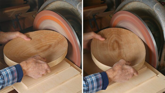
As always with a disc sander, use a light touch.


